decoding La Crosse TX20 Anemometer data with Arduino
Thanks to the excellent work done by John Geek I wrote a small sketch for Arduino to decode and display data coming from the anemometer.
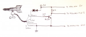
A simple level translator is needed to adapt the signal coming from the anemometer to Arduino board.
The level translator also inverts the signal coming from pin 1 of the anemometer.
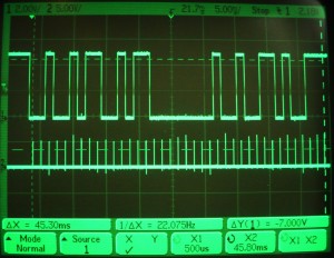
The following picture shows on the top track the frame coming from TX20, on the lower track the sampling signal, used to debug the sketch.
The sketch is a proof of concept, it simply prints out the data coming from the anemometer, and can be used as starting point to develop more complex projects.
#include <avr/io.h>
#include <avr/interrupt.h>

#define _MDEBUG

unsigned int icr1;

void setup() {

// Initialize the digital pin as an output.
// Pin 13 has an LED connected on most Arduino boards
#ifdef _MDEBUG
  pinMode(13, OUTPUT);
#endif

  Serial.begin(9600);
  pinMode(2, INPUT);

  EICRA  = _BV(ISC01);    // set INT0 to trigger on falling edge
  EIMSK = _BV(INT0);     // Turns on INT0

  icr1 = 19500;

  TCCR1A = 0;     // set entire TCCR1A register to 0
  TCCR1B = 0;     // same for TCCR1B
  OCR1A = icr1;
}

volatile int rx=0;
volatile int bitcount=0;
volatile char pin;
volatile unsigned char sa,sb,sd,se;
volatile unsigned int sc,sf;

void loop(){
  char a[90];
  unsigned char chk;

  // Main code loop
  // TODO: Put your regular (non-ISR) logic here

  if (rx){
    chk= ( sb + (sc&0xf) + ((sc>>4)&0xf) + ((sc>>8)&0xf) );chk&=0xf;
    if (sa==4 && sb==se && sc==sf && sd==chk){
      sprintf (a,"%d\t%d\n",sb,sc);
      Serial.write (a);
    }
    rx=0;
  }

}

// pin change interrupt ( start of frame )
ISR (INT0_vect){

  // reset accumulators
  sa=sb=sd=se=0;
  sc=0;

  EIMSK &= ~_BV(INT0);     // disable pin interrupt

  bitcount=41;

  TCCR1B = 0; // stop timer
  TCNT1 = icr1>>1; // set counter
  TIFR1 |= _BV(OCF1A); // clear timer interrupt
  TCCR1B = _BV(WGM12)| _BV(CS10); // start timer
  TIMSK1 |= _BV(OCIE1A);  // enable timer interrupt

}

// timer irq ( bit accumulator )
ISR(TIMER1_COMPA_vect){

  if (bitcount==1){
    TIMSK1 &= ~_BV(OCIE1A); // disable timer interrupt
    EIFR |= _BV(INTF0);     // clear pin interrupt flag
    EIMSK = _BV(INT0);      // enable pin interrupt flag for next frame

  }
  if (bitcount>0){
    pin = digitalRead(2);

    if (bitcount > 41-5){
      // start
      sa = (sa<<1)|pin;
    } else
    if (bitcount > 41-5-4){
      // wind dir
      sb = sb>>1 | (pin<<3);
    } else
    if (bitcount > 41-5-4-12){
      // windspeed
      sc = sc>>1 | (pin<<11);
    } else
    if (bitcount > 41-5-4-12-4){
      // checksum
      sd = sd>>1 | (pin<<3);
    } else
    if (bitcount > 41-5-4-12-4-4){
      // wind dir, inverted
      se = se>>1 | ((pin^1)<<3);
    } else {
      // windspeed, inverted
      sf = sf>>1 | ((pin^1)<<11);
    }


//digitalWrite( 13, digitalRead( 13 ) ^ 1 );
#ifdef _MDEBUG
    digitalWrite( 13, 0 );
    digitalWrite( 13, 1 );
    digitalWrite( 13, 1 );
    digitalWrite( 13, 0 );
#endif
    bitcount--;
    if (bitcount==0){
      // all data received:
      rx=1;
    }
  }
}
Stai leggendo “ decoding La Crosse TX20 Anemometer data with Arduino ”, un post di Fabrizio Zellini
- Pubblicato il
- 8 Febbraio 2015
- Categorie:
- elettronica
15 Commenti
commenta | feed commenti [?] | trackback uri [?]